
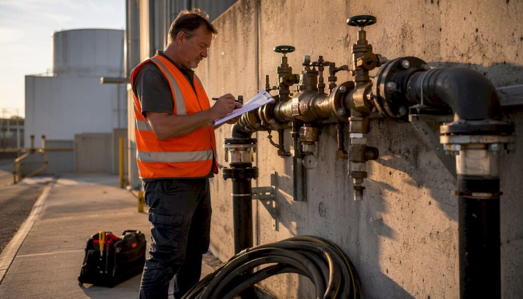
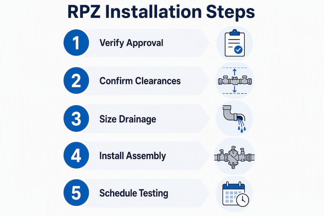
A compliant RPZ installation requires a listed assembly, horizontal orientation, centerline height between 30 and 60 inches, at least 18 inches of clearance below the relief valve, gravity drainage sized to the manufacturer’s flow curves, and a certified initial test filed with your water authority — typically within 10 business days of installation.
Before anything else, confirm your assembly appears on a recognized approval list such as the USC Foundation for Cross-Connection Control and Hydraulic Research list. Pull the manufacturer’s flow curves to size your drain. Then verify permit requirements with your local Authority Having Jurisdiction (AHJ).
Minimum requirements at a glance:
- Centerline height: 30–60 inches above finished floor
- Relief valve clearance: 18 inches minimum below relief valve to floor
- Above-assembly clearance: 12 inches minimum
- Front clearance: 30 inches minimum; back clearance: 8 inches minimum
- Drainage: gravity only (no sump pump unless sized to max relief flow and on emergency power)
- Assembly: must appear on a recognized approval list (USC Foundation)
- Orientation: horizontal unless manufacturer explicitly approves vertical
- Initial test: by a certified tester, results filed with water supplier
Next step: Pull your local AHJ permit requirements and schedule your certified tester before the installation date, not after.
Pro Tip: Schedule your certified tester before the installation date. Waiting until after the physical install to find a tester is the single most common cause of delayed final sign-off.
Table of Contents
- 1. What are the minimum clearances for RPZ installation?
- 2. How do you confirm an RPZ assembly is approved for installation?
- 3. Sizing gravity drainage for RPZ relief valve discharges
- 4. What access and servicing clearances does a certified tester need?
- 5. Vault versus above-grade enclosures: which one meets code?
- 6. Step-by-step installation checklist and testing workflow
- 7. Who can install an RPZ, and who must perform the testing?
- 8. Key U.S. codes, standards, and municipal guidelines for RPZ work
- 9. Sizing the RPZ assembly and understanding pressure loss
- 10. How Southjerseybackflow handles RPZ installs in New Jersey
- Key Takeaways
- The part most installers get wrong
- Southjerseybackflow makes RPZ compliance straightforward in New Jersey
- Authoritative sources to attach to your permit package
1. What are the minimum clearances for RPZ installation?
The numeric clearances most jurisdictions require are specific and non-negotiable. Getting them wrong means a failed inspection and a rework job.
| Clearance | Minimum Requirement |
|---|---|
| Centerline height above floor | 30–60 inches |
| Below relief valve to floor | 18 inches minimum |
| Above assembly | 12 inches minimum |
| Front of device to wall/obstruction | 30 inches minimum |
| Back of device to wall/obstruction | 8 inches minimum (more for side-mounted test cocks) |
Every one of those dimensions serves a purpose. The 18-inch floor clearance keeps the relief valve above standing water and gives a tester room to work. The 30-inch front clearance is about getting tools and hands in without contorting. The 12 inches above the assembly is for operating shutoff valves and pulling check valve internals.
When a centerline exceeds 60 inches, OSHA-compliant fixed platforms or portable scaffolding are required. That adds cost and complexity, so aim for the 30–60-inch window during design.
Orientation and supports:
- Install horizontally unless the specific model carries manufacturer approval for vertical orientation
- Use pipe hangers and supports that do not obstruct test cocks or the relief valve discharge
- Keep all test cocks and the relief valve opening fully accessible without moving any permanent structure
If the distance between the water meter and the RPZ exceeds 10 feet, stencil the feed line “Feed Line to Backflow Preventer — DO NOT TAP” at 5-foot intervals along the exposed pipe.
Pro Tip: Check the specific model’s spec sheet before finalizing the rough-in dimensions. Some assemblies have side-mounted test cocks or relief valves that face the back wall — those require more than the 8-inch baseline back clearance.
2. How do you confirm an RPZ assembly is approved for installation?
An RPZ that is not on a recognized approval list will not pass inspection, period. The USC Foundation for Cross-Connection Control and Hydraulic Research at the University of Southern California maintains the most widely referenced approval list in the United States. Most AHJs require the assembly to appear there before they will issue a permit.
Standards to verify before ordering:
- ANSI/ASSE 1013: The primary product standard for Reduced Pressure Principle Backflow Preventers in the U.S. — confirms the assembly design meets performance requirements
- USC Foundation approval list: Confirms the specific model and size have been tested and listed
- AWWA guidance: AWWA publishes manuals and technical references on cross-connection control that many state programs incorporate by reference
- Local AHJ list: Some municipalities maintain their own approved-assembly lists in addition to the USC Foundation list — check both
Verification checklist before accepting delivery:
- Confirm the model number and size appear on the USC Foundation approval list
- Check the product nameplate for the ASSE 1013 listing mark
- Pull the manufacturer’s spec sheet and confirm it includes head-loss curves and relief-flow curves
- Verify the assembly is approved for the intended orientation (horizontal is standard)
- Confirm the assembly size matches the service line size and the calculated flow demand
For permit submittal: Document the approval list entry, the ASSE listing, and the manufacturer spec sheet. Attach these to the plan set. Inspectors routinely ask for the listing reference at sign-off.
Pro Tip: Download the manufacturer’s full technical data sheet, not just the cut sheet. The full sheet contains the relief-flow curves you need for drain sizing — the cut sheet usually does not.
3. Sizing gravity drainage for RPZ relief valve discharges
Drainage is where most RPZ installations get into trouble. The gravity-drain requirement is absolute: sump pumps are not permitted unless they are sized for the maximum possible relief discharge rate and connected to emergency power. In practice, that exception is rarely met, so plan for gravity drainage from the start.
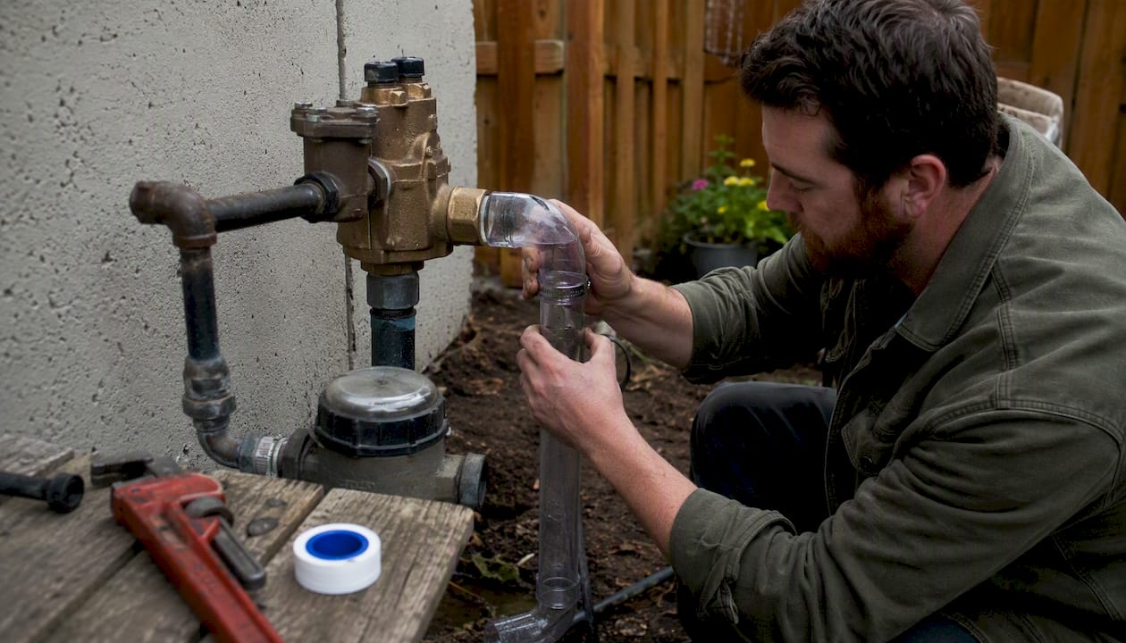
The drain must handle two very different scenarios: the small, intermittent discharge during annual testing, and the full-bore flow from a catastrophic relief valve failure. Size for the catastrophic case.
| Scenario | Sizing Basis |
|---|---|
| Intermittent test discharge | Manufacturer’s flow curve at normal operating pressure |
| Catastrophic relief failure | Manufacturer’s flow curve at maximum supply or on-site pressure (use the higher value) |
| Air gap at relief outlet | Minimum twice the effective opening diameter, never less than 1 inch |
| Discharge pipe termination | Minimum 1 inch above the receiving drain rim |
Use the manufacturer’s relief-flow curves directly. Select the higher of supply pressure or on-site pressure, read the maximum flow rate off the curve, and size the drain pipe for that flow at a gravity slope. For most residential and light-commercial services in the 60–80 psi range, a 3-inch or 4-inch gravity drain is typical, but always confirm against the actual curve.
Additional drainage rules:
- Maintain an air gap between the relief valve opening and any discharge piping — at least twice the effective opening, never less than 1 inch
- Terminate discharge piping a minimum of 1 inch above the receiving drain or above grade flood elevation
- For exterior terminations, use screened louvers, pipe sleeves with flap valves, or scuppers to prevent rodent entry
- When discharging to a sanitary sewer, check local code on whether a backwater valve or trap is required
Pro Tip: Contact the manufacturer’s technical support line and ask for the relief-flow curve for your specific model and size. Give them your maximum supply pressure. They will tell you the peak flow rate in GPM, which you can then use to select drain pipe diameter from a standard hydraulic table.
4. What access and servicing clearances does a certified tester need?
A certified tester arriving for the initial or annual test needs to reach all four test cocks, operate both shutoff valves, and observe the relief valve discharge without using a ladder or moving any permanent structure. If the installation does not allow that, expect a failed test report and a rework order.
Required access elements:
- All test cocks must be reachable from a standing position within the centerline height window
- Both resilient-seated shutoff valves (upstream and downstream) must be operable without obstruction
- The relief valve discharge must be visible to maintenance personnel, either directly or via a water-level alarm or flow indicator
- A bypass arrangement is strongly recommended when service interruptions are unacceptable — size the bypass for the full service demand
Service sequence every tester follows:
- Isolate the assembly using the upstream shutoff
- Attach test equipment to the test cocks
- Perform differential pressure tests across check valves and relief valve
- Document results on the required test form
- Restore service and tag the assembly
The assembly must carry a serialized identification tag per AHJ requirements. The tag typically shows the assembly serial number, model, size, installation date, and tester certification number. The tester will attach or verify this tag at completion and leave a copy of the test form with the property owner.
Pro Tip: Ask your certified tester to walk the rough-in location before the wall is closed or the enclosure is finished. A 10-minute site visit before construction saves hours of rework.
5. Vault versus above-grade enclosures: which one meets code?
Above-grade installations are preferred by virtually every municipal guideline for one straightforward reason: gravity drainage from an RPZ is far easier to achieve when the assembly is above grade. The preference for above-grade insulated enclosures is explicit in most state and municipal guidance, and the practical benefits compound quickly.
Why above-grade heated enclosures win:
- Gravity drainage is direct and reliable — no volume calculations, no pump exceptions
- Prefabricated insulated enclosures with electric heat or heat-trace wire keep the assembly above freezing year-round
- Removable access panels give testers full clearance without confined-space entry
- Inspection friction is lower because AHJs can verify clearances and drainage visually
When a pit (vault) is unavoidable:
Pits are discouraged, but they are allowed when specific conditions are met. The design requirements for pit installations include:
- Watertight construction with manholes extending at least 6 inches above grade
- Manholes positioned to allow natural light into the pit during testing
- Stairway, ladder, or step irons for access
- Crane access provisions for large assemblies
- Floors pitched to drain, with a full-flow screened gravity drain terminating above grade
- For 2-inch and smaller RPZ units, the below-grade floor area and volume must be sufficient to contain a full relief valve failure discharge — 2,000 cubic feet is the commonly cited threshold; for larger units, the volume must provide at least 8 hours before the assembly would be submerged at the maximum discharge rate
Enclosure design minimums (above-grade):
| Feature | Requirement |
|---|---|
| Floor elevation | At least 6 inches above finished grade |
| Heat source | Electric heaters or heat-trace wire for year-round service |
| Lighting | Natural or artificial light required |
| Drainage | Full-flow gravity drain per drainage requirements |
| Access panels | Removable, sized for full clearance around device |
Pro Tip: In cold-weather climates like New Jersey, a heated above-grade enclosure almost always costs less over a 10-year horizon than a pit — lower inspection friction, no confined-space entry, and no emergency-power pump requirement.
6. Step-by-step installation checklist and testing workflow
Treat this as two separate phases. The mechanical install and the certified test are distinct jobs, and the filing deadline starts the moment the test is complete.
Phase 1: Pre-installation
- Confirm the assembly model is on the USC Foundation approval list and carries the ASSE 1013 listing
- Pull manufacturer head-loss and relief-flow curves; size the drain pipe
- Prepare a dimensioned site plan and vertical cross-section showing all clearances, floor drains, and nearby objects (electrical panels, boilers, etc.)
- Submit plans to the AHJ and obtain the required permit
- Confirm the certified tester’s schedule before breaking ground
Phase 2: Physical installation
- Set the assembly at the correct centerline height (30–60 inches), horizontal orientation
- Install pipe supports and hangers; verify no support blocks a test cock or the relief valve
- Connect gravity drain with proper air gap and termination height
- Install upstream and downstream resilient-seated shutoff valves
- Stencil feed line if meter-to-RPZ distance exceeds 10 feet
- Attach the serialized identification tag per AHJ requirements
Phase 3: Testing and filing
- Certified tester performs initial test — differential pressure across both check valves and the relief valve
- Tester completes the required test form and attaches the tag
- Property owner or tester files the test results with the water supplier — many programs require filing within 10 business days
- Schedule final building inspection; have the permit, approval documentation, and test report on-site
Common reasons for failing initial sign-off:
- Relief valve clearance below 18 inches
- Drain not gravity-fed or undersized
- Assembly not on the AHJ’s approved list
- Test report not filed within the required window
- Missing or incorrect identification tag
Pro Tip: Keep a physical copy of the test report, the approval list entry, and the permit on-site through the final inspection. Inspectors who cannot find the paperwork will fail the inspection even when the hardware is correct.
7. Who can install an RPZ, and who must perform the testing?
These are two different questions with two different answers, and mixing them up creates real compliance exposure.
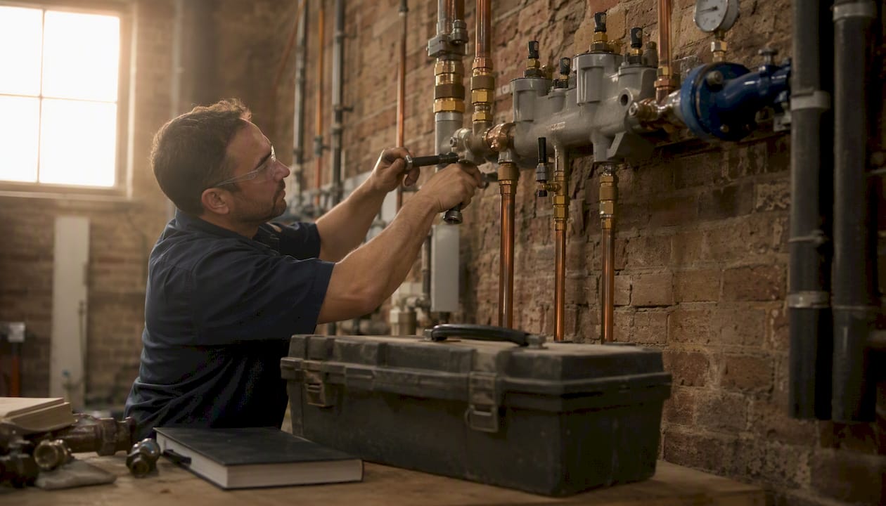
The install: Most jurisdictions allow any licensed plumber to perform the physical installation of the RPZ assembly, piping, supports, and drain. The plumber does not need a separate backflow certification to do the mechanical work — a standard plumbing license and the required building permit are sufficient in most states.
The test: Testing is a separate, credentialed activity. The initial test and every annual test must be performed by a tester who holds a current backflow prevention certification recognized by the AHJ. That tester must be listed with the water supplier or municipality, and the test results must be submitted on the AHJ’s required form.
| Responsibility | Who Performs It |
|---|---|
| Physical installation (piping, supports, drain) | Licensed plumber |
| Permit application and plan submittal | Licensed plumber or engineer |
| Initial and annual testing | Certified backflow tester (AHJ-listed) |
| Test report filing with water supplier | Certified tester or property owner (varies by AHJ) |
| Annual compliance tracking | Property owner or facility manager |
| Repairs and rebuilds after failed test | Licensed plumber or certified tester (varies by AHJ) |
Some jurisdictions require the certified tester to also hold a plumbing license. Others separate the two credentials entirely. Check with your local water supplier before hiring — the wrong credential on the test report will void the filing.
8. Key U.S. codes, standards, and municipal guidelines for RPZ work
Every permit package for an RPZ installation should reference at least the following documents. Inspectors know these sources and will ask for them.
Primary standards and references:
- USC Foundation for Cross-Connection Control and Hydraulic Research (University of Southern California): Maintains the most widely recognized approval list for backflow prevention assemblies in the U.S. Any assembly not on this list faces an uphill permit battle in most jurisdictions.
- ANSI/ASSE 1013: The product performance standard for Reduced Pressure Principle Backflow Preventers. Listing under this standard confirms the assembly design has been independently tested.
- AWWA Cross-Connection Control Manual: Published by the American Water Works Association, this manual provides technical guidance on program administration, device selection, and installation requirements. Many state programs adopt it by reference.
- State Department of Health cross-connection manuals: New York State DOH publishes detailed installation design guidelines that are widely used as a model by neighboring states, including New Jersey. These cover clearances, drainage, vault design, and testing requirements in detail.
- Local municipal installation guides: Many water suppliers publish their own installation guides that incorporate state DOH requirements and add local specifics (filing deadlines, approved tester lists, required form numbers). The Menlo Park guide, for example, specifies a 10-business-day filing window after testing.
- International Plumbing Code (IPC) Section 608 / IRC Section P2902: The IPC and IRC set minimum requirements for backflow prevention device selection, installation height, air gaps, and annual inspection. Most U.S. jurisdictions adopt one of these model codes with local amendments.
For permit submittals: Attach the USC Foundation approval list entry, the ASSE 1013 listing reference, and the relevant section of your state or municipal cross-connection manual. Inspectors want to see that the designer has read the actual standard, not just cited it.
The RPZ relies on a pressure differential — the reduced zone is maintained at least approximately 2 psi lower than inlet pressure. That differential is what makes annual testing mandatory: a failed check valve or a fouled relief valve can collapse that differential without any visible sign at the tap.
For NJ-specific plumbing code requirements, the state adopts the Uniform Construction Code with local amendments — always verify the current adopted edition with your municipal building department.
9. Sizing the RPZ assembly and understanding pressure loss
Choosing the right assembly size is not just about matching the pipe diameter. Head loss through an RPZ is significant, and undersizing creates pressure problems downstream while oversizing can cause nuisance relief valve dripping at low flow.
Hydraulic sizing basics:
- Pull the manufacturer’s head-loss curve for the specific model and size
- Plot your design flow rate against the curve to find the pressure drop across the assembly
- If the resulting downstream pressure is insufficient for the application, consider a larger assembly or a parallel (manifolded) arrangement
- For large services where a single assembly creates unacceptable head loss, two assemblies in parallel are often more practical than one oversized unit
Pressure differential and relief operation:
The RPZ maintains the reduced zone at least approximately 2 psi below inlet pressure. If inlet pressure fluctuates significantly, the relief valve can drip intermittently — this is normal operation, not a failure. However, persistent dripping between tests usually signals a fouled first check valve or a relief valve that needs service.
| Condition | Likely Cause | Action |
|---|---|---|
| Intermittent relief drip | Normal pressure fluctuation | Monitor; test at next annual cycle |
| Continuous relief drip | First check valve fouled or relief valve seat worn | Schedule repair |
| No pressure downstream | Second check valve failed closed | Isolate and repair immediately |
A soft-seated check valve installed upstream of the RPZ can stabilize fluctuating supply pressure and reduce nuisance relief dripping. This is a practical mitigation on services with variable municipal pressure.
For drain sizing from pressure data: read the maximum relief flow rate from the manufacturer’s curve at your highest expected supply pressure, then size the gravity drain pipe to carry that flow at a 1/4-inch-per-foot slope. A 3-inch drain handles roughly 40–50 GPM at that slope; a 4-inch drain handles roughly 80–100 GPM. Always verify against the actual curve numbers for your assembly.
Understanding RPZ differential pressure behavior helps facility managers recognize when a device needs service before the annual test cycle flags it.
10. How Southjerseybackflow handles RPZ installs in New Jersey
New Jersey properties face the same federal and ANSI/ASSE standards as the rest of the country, but the local filing process has its own specifics. The state adopts the Uniform Construction Code, and individual water suppliers maintain their own approved-tester lists and test-form requirements.
The typical NJ process Southjerseybackflow follows:
- Permit check: Confirm the local AHJ’s permit requirements and the water supplier’s approved-assembly list before ordering equipment
- Assembly selection: Verify the model against the USC Foundation approval list and the local water supplier’s requirements; pull manufacturer flow curves for drain sizing
- Enclosure preference: In New Jersey’s cold winters, above-grade heated enclosures are the standard recommendation — they eliminate freeze risk, simplify gravity drainage, and reduce inspection friction
- Physical installation: Set clearances, orientation, supports, and gravity drain per the numeric minimums above
- Certified initial test: Southjerseybackflow’s certified testers perform the initial differential pressure test, complete the required test form, and attach the serialized tag
- Filing: Test results are filed directly with the county water authority or water supplier, typically within the required window
Southjerseybackflow handles the full scope: RPZ installation, enclosure supply and installation, certified testing, test report filing, and ongoing annual compliance. For multi-property clients, consolidated billing and coordinated filing schedules are available.
Pro Tip: If you received a compliance notice from your water supplier, the clock is already running. Southjerseybackflow can pull the permit, install the assembly, test it, and file the report as a single coordinated job — faster than managing three separate contractors.
Key Takeaways
A compliant RPZ installation depends on five non-negotiables: a listed assembly, correct clearances, gravity drainage sized to manufacturer flow curves, horizontal orientation, and a certified initial test filed on time.
| Point | Details |
|---|---|
| Clearances are fixed minimums | 30–60" centerline, 18" below relief valve, 12" above assembly, 30" front, 8" back. |
| Gravity drainage is mandatory | Size drain to catastrophic relief flow using manufacturer curves; sump pumps require emergency power. |
| Assembly must be listed | Verify the model on the USC Foundation approval list and confirm ANSI/ASSE 1013 listing before ordering. |
| Certified tester required | Initial and annual tests must be performed by an AHJ-listed certified tester, not the installing plumber. |
| Southjerseybackflow | Handles installation, enclosure, certified testing, and direct filing with NJ water authorities as one job. |
The part most installers get wrong
The clearance numbers and the listing requirements get most of the attention in code discussions, and they should. But the failure mode that actually causes the most rework is not a clearance violation — it is inadequate drainage planning.
Installers routinely size the drain for the test discharge (a small, intermittent flow) and forget that the drain must also handle a catastrophic relief valve failure. That failure scenario can push hundreds of gallons per minute through a 3/4-inch relief valve opening. A 2-inch floor drain that handles the test just fine will flood a mechanical room in minutes under a full failure. The manufacturer’s flow curves are not optional documentation — they are the only reliable basis for sizing that drain.
The second pattern worth flagging: installations that are mechanically correct but fail inspection because the certified tester was not scheduled until after the final inspection date. Testing is not a formality you add at the end. It is a mandatory step with a filing deadline, and that deadline runs from the test date, not the inspection date. Scheduling the tester before construction starts is the single most reliable way to avoid a delay.
Above-grade heated enclosures also deserve more credit than they typically get. The instinct to put the RPZ in a pit is understandable — it keeps the assembly out of sight and out of the way. But pits create confined-space entry requirements, complicate gravity drainage, and add volume calculations that most designers do not want to deal with. A well-built above-grade enclosure with heat trace and removable panels is easier to inspect, easier to test, and easier to drain. AHJs know this, which is why above-grade installations consistently move through plan review faster.
Southjerseybackflow makes RPZ compliance straightforward in New Jersey
Getting an RPZ installed correctly in New Jersey means coordinating a permit, a listed assembly, a certified tester, and a filing deadline — all while keeping the job on schedule. Southjerseybackflow handles every step of that process as a single engagement: permit coordination, assembly selection from the USC Foundation approval list, above-grade heated enclosure supply and installation, certified differential pressure testing, serialized tagging, and direct filing of test reports with your county water authority.

Property owners and facility managers who hire Southjerseybackflow leave the job with a complete compliance package: the test report, the permit sign-off, the tester’s certification documentation, and the assembly tag. No chasing three separate contractors. No missed filing deadlines.
If your water supplier has already sent a compliance notice, the timeline is tighter than you think. Book your backflow testing and compliance service with Southjerseybackflow and get the permit, install, test, and filing handled as one coordinated job.
Authoritative sources to attach to your permit package
The documents below are the most commonly cited references for RPZ installation in the United States. Attach the relevant sections to your permit submittal and keep them on-site through final inspection.
Clearances and general installation design:
- Guidelines for Designing Backflow Prevention Assembly Installations (NYSDOH) — covers numeric clearances, drainage requirements, vault design, and enclosure standards; widely used as a model by NJ and other northeastern states
- Brunswick NY Backflow Prevention Design Guidelines — detailed municipal guide with clearance tables, drainage sizing rules, and pit/enclosure requirements
Testing, filing, and certification:
- Menlo Park Backflow Device Installation Guidelines — covers certified tester requirements, test form submission, and the 10-business-day filing window
- KUB Backflow Specifications (RPZ, DC, DCDA) — technical specifications including pressure differential requirements and annual testing rationale
Code and standards references:
- ICC CodeNotes: Backflow Preventers and Protection of Water Supply — IPC and IRC requirements for RPZ installation, air gaps, annual inspection, and test procedures per ASSE 5013/5015 series
- NYSDOH Backflow Design Guidelines (municipal PDF) — covers feed-line labeling requirements and OSHA platform requirements for high installations
- Tonawanda Municipal Backflow Installation Guidelines — above-grade enclosure design requirements and soft-seated check valve guidance
USC Foundation and ANSI/ASSE:
The USC Foundation for Cross-Connection Control and Hydraulic Research approval list and the ANSI/ASSE 1013 standard are not freely available as direct-link PDFs, but both are referenced by name in every state cross-connection manual above. Request the current USC Foundation approval list directly from the USC Foundation or through your water supplier’s cross-connection control program.
Pingback: PVB vs RPZ: Which Backflow Preventer Does Your Property Need?
Pingback: Why Your RPZ Relief Valve Is Dumping Water (And When to Worry)
Pingback: Size RPZ Drains for 150 GPM Relief: For Plumbers and Property Managers